The Best Guide To Wedge Barriers
Wiki Article
The 5-Second Trick For Wedge Barriers
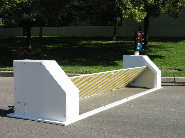
14 and the surface area 12 to which the obstacle 10 is safeguarded might be made from concrete - Wedge Barriers. 2, the obstacle 10 is installed to or consists of an anchor or subframe (e. g., support 30 received FIG. 2 )secured under the surface area 12. The bather 10 might be bolted to the support or protected to the anchor by other mechanical fasteners. In the illustrated embodiment, the obstacle 10 includes a wedge plate 16, which includes a portion that is considerably identical with the surface 12 when the barrier 10 remains in the pulled back setting. To put it simply, lorries or individuals may overlook the barrier 10 when the barrier 10 remains in the pulled back position and experience minor elevation relative to the surface area 12 while on the barrier 10. As discussed in information below, when the barrier 10 is in the deployed setting, the wedge plate 16 is held and supported in an elevated setting by a lifting system of the barrier 10. Additionally, the parts 18 may be bolted or otherwise mechanically paired to each other. In this manner, repair service or replacement of several components 18 might be streamlined and streamlined. That is, repair or substitute of single elements 18 may be done a lot more rapidly, conveniently, and expense effectively. FIG. In particular embodiments, the support 30 might be a steel frame consisting of plates, beam of lights(e. g., I-beams ), and/or various other structures that are protected within the structure 14, which may be concrete. At the surface area 12, a top side 28 of the anchor 30 may go to least partially revealed , thus making it possible for the attachment of the barrier 10 to the support 30. g., threaded openings)in several beam of lights or plates of the support 30 might be exposed to the surface 12. In this way, screws 32 or other mechanical fasteners might be made use of to secure the barrier 10 to the anchor 30. As the barrier 10 is installed to the surface area 12 of the structure go now 14, collection of debris and other material underneath the obstacle might be reduced, and elements of the bather 10 may not be exposed to listed below grade environments. As shown by referral numeral 52, the training mechanism 50 consists of components disposed underneath the wedge plate 16. For instance, the parts 52 beneath the wedge plate 16 may include an electromechanical actuator, a webcam, one or more camera surface areas, etc. In addition, the training device 50 consists of a springtime assembly 54
The spring rod 58 is coupled to a webcam(e. g., webcam 80 displayed in FIG. 4) of the training mechanism 50. The springtimes 60 disposed about the spring rod 58 are kept in compression by springtime sustains 62, including a fixed springtime assistance 64. That is, the set spring assistance 64 is taken care of loved one to the structure 14 and the rest of the bather 10.
5 Easy Facts About Wedge Barriers Explained
g., spring assistance 65 )might be dealt with to the end of the spring rod 58 to enable compression of the springs 60. As the springtimes 60 are compressed in between the spring sustains 62, the spring assembly 54 creates a force acting Related Site upon the cam combined to the springtime rod 58 in a direction 66. As an example, the remaining pressure put on the cam to release the wedge plate 16 might be provided by an electromechanical actuator 84 or other actuator. Therefore, the springtime setting up 54 and the look these up actuator 84(e. g., electromechanical actuator)may operate together to convert the web cam and lift the wedge plate 16.
As stated above, in the deployed setting, the wedge plate 16 offers to block gain access to or traveling past the obstacle 10. The barrier 10(e. g., the wedge plate 16 )may obstruct pedestrians or lorries from accessing a home or path. If a lorry is taking a trip towards the deployed wedge plate 16(e. For example, in one condition, the safety and security legs 86 may be extended duringmaintenance of the barrier 10.
Report this wiki page